Examples
A sequence of examples, from a simple mass attached to a spring-damper element to a full segmented tether model with real-out and aerodynamic drag attached.
| Name | Description | Learning objective |
|---|---|---|
| Tether_01 | Mass, thrown upwards, then falling | Learn how to define a model, simulate it and plot the results |
| Tether_02 | Mass, attached to a spring-damper | Learn how to model a spring in 3D |
| Tether_03 | Mass, with non-linear spring-damper | Learn how to model DAE systems with discontinuities |
| Tether_04 | Multi-segment tether | Learn how to use arrays of equations |
| Tether_05 | Segmented tether with correct force distribution | Learn how to distribute the spring force over two masses |
| Tether_06 | Multi-segment tether reeling out | Learn to model a tether with changing unstretched length |
| Tether_07 | Segmented tether with aerodynamic drag | Learn how to model tether drag |
| Tether_08 | Tether with arbitrary endpoints | Learn how to use a steady state solver |
| Tether_09 | Labeled tether shape diagram | Learn how to annotate a plot with LaTeXStrings |
| Tether_10 | Re-usable tether component | Learn how to build composable, acausal components |
| Tether_11 | Kite flying a circular trajectory | Learn how to drive a tether end point along a prescribed trajectory |
Nomenclature:
- ODE: Ordinary differential equations
- DAE: Differential algebraic equations
Mass, thrown upwards, then falling
Use the provided script to start Julia from the Tethers.jl folder:
cd repos/Tethers.jl
./bin/run_julia
From the Julia prompt, run the simulation:
include("examples/Tether_01.jl")You should see a plot similar to:
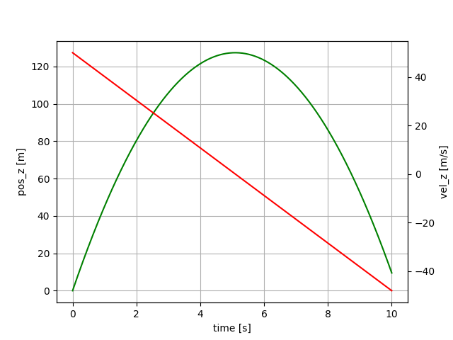
This example shows a mass that is thrown upwards, slows down and then falls.
Julia code: Tether_01.jl
These differential equations define the model:
D = Differential(t)

eqs = vcat(D.(pos) ~ vel,
           D.(vel) ~ acc,
           acc    .~ G_EARTH)
The term D.(pos) means "Apply the differential D(t) to all elements of the vector pos". The second term defines that the differential of the velocity vector must be equal to the acceleration. For equality in symbolic equations the character ~ has to be used, because the character = has the meaning "assign a value to a variable" which is not what we are doing here. The third equation means that all elements of the acceleration vector must be equal to the elements of the gravity vector. We end up with an array of 3x3` equations.
The next lines are:
@named sys = System(eqs, t)
simple_sys = mtkcompile(sys)
This means we create a named ordinary equation system, depending on t. Then we simplify the system symbolically (order reduction). If you type sys in the Julia REPL (command line) you can see that the original system had 9 equations, the second line above created a system with only six equations. This step helps to speed up the simulation and often also removes algebraic loops which makes the ODE a lot simpler to solve numerically later on.
Now the parameters of the integrator are defined:
duration = 10.0
dt = 0.02
tol = 1e-6
ts    = 0:dt:duration
The time step $dt$ is the interval in which the solution shall be stored, NOT the time step of the integrator. The integrator uses a variable time step which can be much smaller or much larger as determined by the required tolerance, in this example set to $tol=10^{-6}$. The variable $ts$ is a range object defining the sampling times for the result.
In the next lines, we define the ODE problem and finally, we solve it using the FBDF solver with the given parameters. The second parameter defines the initial conditions. We use nothing here because we defined the initial conditions already in the model.
prob = ODEProblem(simple_sys, nothing, (0.0, duration))
@time sol = solve(prob, FBDF(), dt=dt, abstol=tol, reltol=tol, saveat=ts)
The macro @time measures the compilation and execution time of calling the function solve(). The function is compiled only when called the first time.
Python version as comparison
From the Julia prompt execute:
run_python("Tether_01")This will install Python, Matplotlib and Assimulo and execute the script Tether_01.py.
Python code: Tether_01.py
If you compare the Python and the Julia scripts you can see that:
- the Julia script is shorter and easier to read
- Julia is about 16 times faster when running the simulation
Mass, attached to a spring-damper
From the Julia prompt, run the simulation:
include("examples/Tether_02.jl")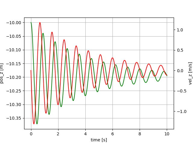
Mass, attached to a spring-damper element. One end of the spring is attached at the origin, the second end is attached to the mass. Mass initially below the origin, spring un-stretched. Z-axis pointing upwards.
After running it, type sys and simple_sys in the REPL to see the representation of the system and the simplified system. You can see that the original system has 17 equations, which have been automatically simplified to 6 equations in simple_sys.
Julia code: Tether_02.jl
Mass, with non-linear spring damper
include("examples/Tether_03.jl")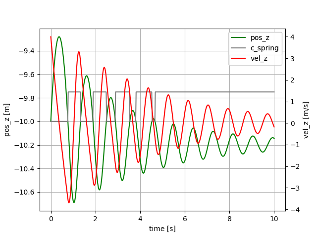
Mass, attached to a non-linear spring-damper element. One end of the spring is attached at the origin, and the second end is attached to the mass. Mass initially below the origin, spring un-stretched. Z-axis pointing upwards.
Initial velocity $4 m/s$ upwards. The compression stiffness is zero. The grey line shows that the stiffness is zero at the beginning, and has the nominal value at the end. Example: Tether_03.jl.
Thanks to the package ModelingToolkit.jl the system description is very compact and readable:
eqs = vcat(D.(pos)      ~ vel,
           D.(vel)      ~ acc,
           norm1        ~ norm(pos),
           unit_vector  ~ -pos/norm1,         # direction from point mass to origin
           spring_vel   ~ -unit_vector ⋅ vel,
           c_spring     ~ c_spring0 * (norm1 > abs(l0)),
           spring_force ~ (c_spring * (norm1 - abs(l0)) + damping * spring_vel) * unit_vector,
           acc          ~ G_EARTH + spring_force/mass)
The same in Python: Python code: Tether_03.py.
Using a callback
By using a callback to detect exactly when the transition from a stiff tether segment to a loose tether segment happens we can increase the accuracy of the simulation. Julia code: Tether_03b.jl.
We only have to add the following lines of code:
function condition(u, t, integrator) # Event when condition(u,t,integrator) == 0
    norm(u[1:3]) - abs(L0)
end
function affect!(integrator)
    println(integrator.t)            # Not needed, just to show that the callback works
end
cb = ContinuousCallback(condition, affect!)
and add the parameter callback = cb to the line that calls the solver:
sol = solve(prob, FBDF(), dt=dt, abstol=tol, reltol=tol, saveat=ts, callback = cb)Using a callback with Python
In Python you would have to add the following attribute:
sw0 = [vel_1[2] > 0] # array of booleans; true means the tether segment is loose (l < l_0)and the following methods:
    def state_events(self, t, y, yd, sw):
        """
        This is our function that keeps track of our events. When the sign
        of any of the events has changed, we have an event.
        """
        # calculate the norm of the vector from mass1 to mass0 minus the initial segment length
        event_0 = np.linalg.norm(y[3:6]) - L_0
        return np.array([event_0])

    def handle_event(self, solver, event_info):
        """
        Event handling. This functions is called when Assimulo finds an event as
        specified by the event functions.
        """
        state_info = event_info[0] # We are only interested in state events
        if state_info[0] != 0:     # Check if the first event function has been triggered
            if solver.sw[0]:       # If the switch is True the pendulum bounces
                print(solver.t)
Example: Tether_03b.py. As you can see, logging of calculated variables is not possible with Assimulo (easy with ModelingToolkit in Julia). You need to re-calculate them after the simulation.
Benchmarking non-linear simulation
Using a callback slows the simulation down, but not much. Try it out:
include("examples/Tether_03c.jl")Output on a fast PC:
Solving the system without callback...
  0.000606 seconds (8.06 k allocations: 257.672 KiB)
Press any key...

Solving the system with callback...
  0.000741 seconds (9.93 k allocations: 365.812 KiB)
If you zoom in to the points in time where pos_z crosses -10m
you should see a difference...
In this example, the gain of accuracy is very small, but that can be different in other simulations. For benchmarking we call solve twice: The first call ensures that the code is compiled, and the second call measures the execution time of the code.
Python The script, which executes the Python code with callbacks:
run_python("Tether_03b")reports 31 ms for solving the problem (without printing). Without callbacks:
run_python("Tether_03")still, 20 ms are needed.
Multi-segment tether
Using 2D arrays of variables allows to simulate a multi-segment tether:
@variables pos(t)[1:3, 1:segments+1]  = POS0
@variables vel(t)[1:3, 1:segments+1]  = VEL0
@variables acc(t)[1:3, 1:segments+1]
In this case, it is important to calculate the initial conditions of each particle such that they are physically feasible:
G_EARTH::Vector{Float64} = [0.0, 0.0, -9.81]    # gravitational acceleration     [m/s²]
L0::Float64 = 10.0                              # initial segment length            [m]
V0::Float64 = 4                                 # initial velocity of lowest mass [m/s]
segments::Int64 = 2                             # number of tether segments         [-]
POS0 = zeros(3, segments+1)
VEL0 = zeros(3, segments+1)
for i in 1:segments+1
    POS0[:, i] .= [0.0, 0, -(i-1)*L0]
    VEL0[:, i] .= [0.0, 0, (i-1)*V0/segments]
end
The first example of such a model is the script Tether_04.jl which is derived from the last example.
Segmented tether with correct force distribution
In the script Tether_05.jl, the spring force is distributed correctly on the two masses attached to the spring as shown here:
# loop over all tether particles to apply the forces and calculate the accelerations
for i in 1:(segments+1)
    global eqs2; local eqs
    eqs = []
    if i == segments+1
        push!(eqs, total_force[:, i] ~ spring_force[:, i-1])
        push!(eqs, acc[:, i]         ~ G_EARTH + total_force[:, i] / (0.5 * mass))
    elseif i == 1
        push!(eqs, total_force[:, i] ~ spring_force[:, i])
        push!(eqs, acc[:, i]         ~ zeros(3))
    else
        push!(eqs, total_force[:, i] ~ spring_force[:, i-1] - spring_force[:, i])
        push!(eqs, acc[:, i]         ~ G_EARTH + total_force[:, i] / mass)
    end
    eqs2 = vcat(eqs2, reduce(vcat, eqs))
end
We loop over the particles. On the first and the last particle only one spring force is acting. On the other particles, two spring forces are acting in the opposite direction. Because the first particle is fixed we set its acceleration to zero.
Julia code: Tether_05.jl
Python code: Tether_05.py
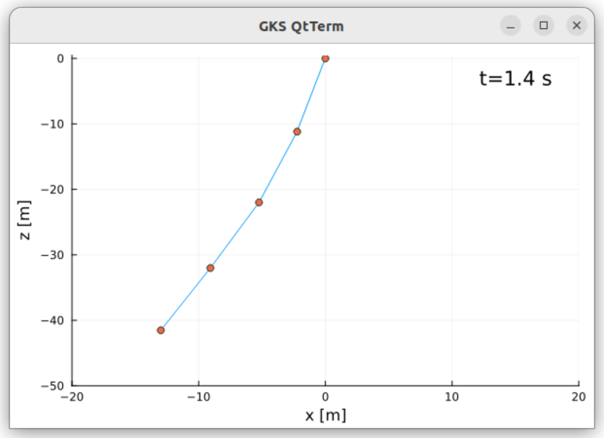
Finally, in this example, we plot the result dynamically as 2D video. Screenshot:
Multi-segment tether reeling out
In this example, we assume a constant reel-out speed of $V_{RO}=2m/s$. When reeling out the following values need to be dynamically calculated:
- unstretched length of a tether segment
- mass of the tether segment
- spring constant
- damping constant
We do this in the following way at line 76ff:
length            ~ L0 + V_RO*t
m_tether_particle ~ mass_per_meter * (length/segments)
c_spring          ~ C_SPRING / (length/segments)
damping           ~ DAMPING  / (length/segments)
where L0 is the unstretched length of the complete tether at $t=0$.
Julia code: Tether_06.jl
The IDA solver, used for Python has a very high numerical damping. Therefore we had to multiply the damping coefficient with a factor of $0.045$ to achieve a more-or-less realistic result.
Python code: Tether_06.py
Refactoring the code, add a Settings struct and splitting it into functions
Julia code: Tether_06b.jl.
If you want to have fast code, that can be reused and tested using unit tests, then it is better to put your code in functions and to avoid global variables. We demonstrate that in this example.
First, the settings are stored in a struct type:
@with_kw mutable struct Settings @deftype Float64
    g_earth::Vector{Float64} = [0.0, 0.0, -9.81] # gravitational acceleration     [m/s²]
    l0 = 50                                      # initial tether length             [m]
    v_ro = 2                                     # reel-out speed                  [m/s]
    d_tether = 4                                 # tether diameter                  [mm]
    rho_tether = 724                             # density of Dyneema            [kg/m³]
    c_spring = 614600                            # unit spring constant              [N]
    damping = 473                                # unit damping constant            [Ns]
    segments::Int64 = 5                          # number of tether segments         [-]
    α0 = π/10                                    # initial tether angle            [rad]
    duration = 10                                # duration of the simulation        [s]
    save::Bool = false                           # save png files in folder video
end
When defining a struct it is good to give a concrete type to each field. Here, we use Float64 as default, as defined in the first line. Apart from this type we also use the type Int64 for integer values and Bool for a boolean value.
Then we split the code into the functions:
function calc_initial_state(se)           # determine the initial state
function model(se)                        # create the model
function simulate(se, simple_sys)         # run the simulation
function play(se, sol, pos)               # play the simulation result, the solution
function main()                           # the main program, calling all the other functions
The main() function looks like this:
function main()
    se = Settings()
    simple_sys, pos, vel = model(se)
    sol = simulate(se, simple_sys)
    play(se, sol, pos)
end
Using a callback
By using a callback to detect exactly when the transition from a stiff tether segment to a loose tether segment happens we can increase the accuracy of the simulation. Julia code: Tether_06c.jl.
The following lines had to be added:
local cb
for i in 1:se.segments
    cbi = [norm([pos[1, i+1] - pos[1, i], pos[2, i+1] - pos[2, i], pos[3, i+1] - pos[3, i]]) ~ abs(se.l0)/se.segments]
    if i == 1
        cb = cbi
    else
        cb = vcat(cb, cbi)
    end
end
@named sys = System(reduce(vcat, Symbolics.scalarize.(eqs2)), t; continuous_events = cb)
MTK 11 note: In ModelingToolkit v11, the broadcast form .~ for array equations that are later processed with Symbolics.scalarize no longer produces valid Equation objects. The spring force assignment must use ~ instead of .~:
# MTK 11: use ~ instead of .~ for array equations used with Symbolics.scalarize
spring_force[:, i]   ~ (c_spr[i] * (norm1[i] - (length/se.segments))
                        + damping * spring_vel[i]) * unit_vector[:, i]
Segmented tether with aerodynamic drag
In the script Tether_07.jl, the tether drag has been added.
The following lines calculate the tether drag force:
v_app_perp[:, i]   ~ v_apparent[:, i] - (v_apparent[:, i] ⋅ unit_vector[:, i]) .* unit_vector[:, i],
norm_v_app[i]      ~ norm(v_app_perp[:, i]),
half_drag_force[:, i] ~ 0.25 * se.rho * se.cd_tether * norm_v_app[i] * (norm1[i]*se.d_tether/1000.0)
In the following for loop the spring and drag forces are applied to the particles:
    for i in 1:(se.segments+1)
        eqs = []
        if i == se.segments+1
            push!(eqs, total_force[:, i] ~ spring_force[:, i-1] + half_drag_force[:, i-1])
            push!(eqs, acc[:, i]         ~ se.g_earth + total_force[:, i] / (0.5 * m_tether_particle))
        elseif i == 1
            push!(eqs, total_force[:, i] ~ spring_force[:, i] + half_drag_force[:, i])
            push!(eqs, acc[:, i]         ~ zeros(3))
        else
            push!(eqs, total_force[:, i] ~ spring_force[:, i-1] - spring_force[:, i]
                                           + half_drag_force[:, i-1] + half_drag_force[:, i])
            push!(eqs, acc[:, i]         ~ se.g_earth + total_force[:, i] / m_tether_particle)
        end
        eqs2 = vcat(eqs2, reduce(vcat, eqs))
    end
If you run the example you can see that the aerodynamic drag adds a lot of damping, the oscillations nearly die out in about 30s.
Tether with arbitrary endpoints
This example is the same as the last one, but you can freely choose:
- both end-points
- if the end-points are fixed or if they just define the initial position
A steady-state solver is used to solve the initial tether shape, based on the endpoints. If both endpoints are fixed you get a catenary line, deformed by the wind. This is useful for model verification.
See: Tether_08.jl
Two versions of the model are implemented, with the signatures:
function model(se; p1=[0,0,0], p2=nothing, fix_p1=true, fix_p2=false)and
function model(se, p1, p2, fix_p1, fix_p2, POS0, VEL0)The first version calls
- the model with fixed endpoints and zero reel-out speed
- the steady-state solver
- and then the model with the initial positions (POS0) found by the steady-state solver, using the original values of
fix_p1,fix_p2and the original reel-out speed.
The body of this function is defined as:
# straight line approximation for the tether
POS0, VEL0 = calc_initial_state(se; p1, p2)
# find steady state
v_ro = se.v_ro      # save the reel-out speed
se.v_ro = 0         # v_ro must be zero, otherwise finding the steady state is not possible
local sol1, pos
try
    simple_sys, sys, pos, =  model(se, p1, p2, true, true, POS0, VEL0)
    tspan = (0.0, se.duration)
    prob = ODEProblem(simple_sys, nothing, tspan)
    prob1 = SteadyStateProblem(prob)
    sol1 = solve(prob1, DynamicSS(FBDF(autodiff=false)))
finally
    se.v_ro = v_ro  # restore the reel-out speed, also if the steady state solver failed
end
SciMLBase.successful_retcode(sol1) ||
    error("Steady state solver failed with return code $(sol1.retcode)!")
POS0 = sol1[pos]
# create the real model
model(se, p1, p2, fix_p1, fix_p2, POS0, VEL0)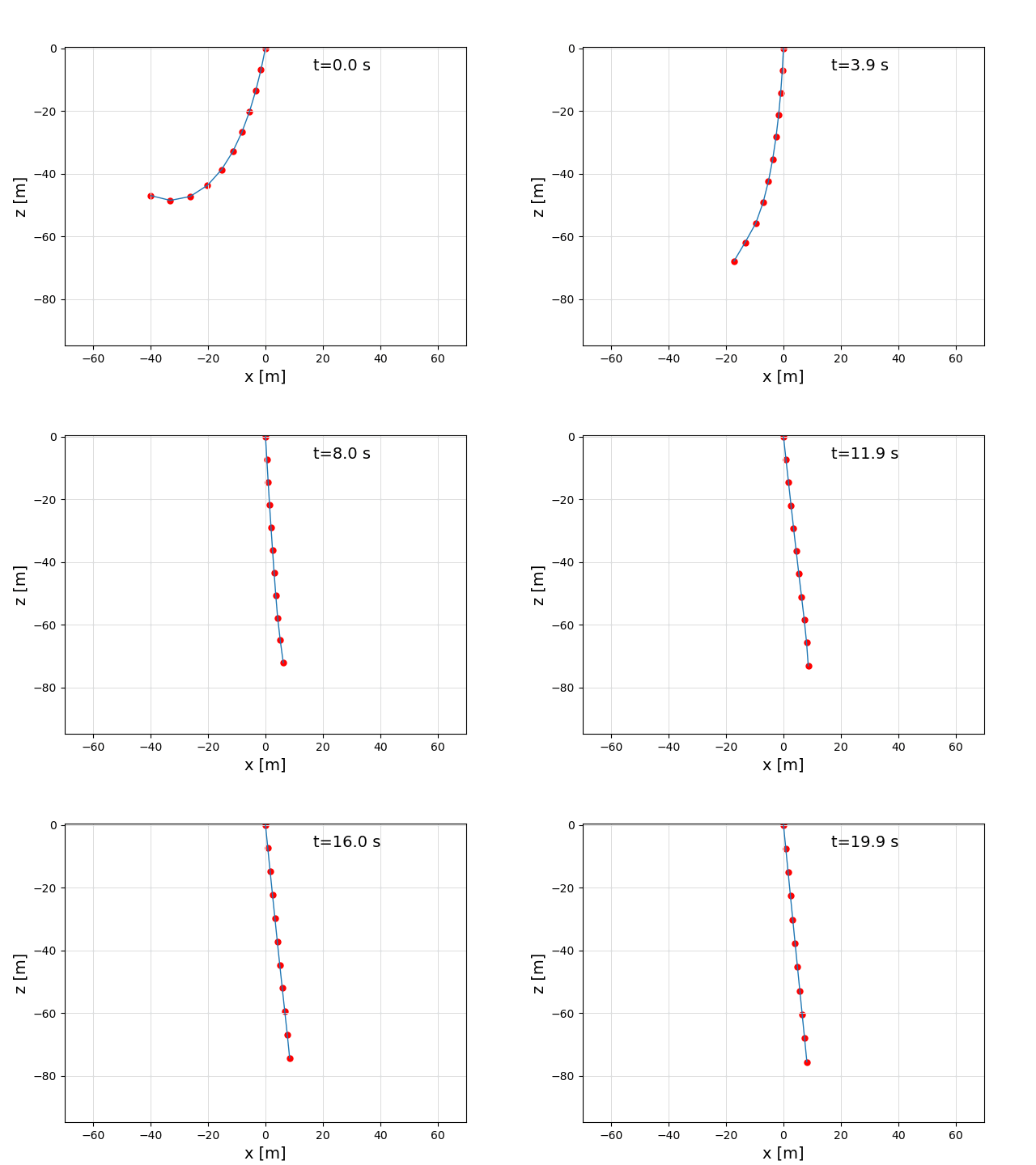
The following call was used to create this video: main(p2=[-40,0,-47], fix_p2=false), with a setting of v_ro = 0.3 m/s.
In the video, you can at the beginning nicely see the catenary line which is a result of the steady state solver, and then the normal dynamic simulation, which results in a line that is pushed to the right by the wind.
Labeled tether shape diagram
This example re-uses the model of Tether with arbitrary endpoints to compute the steady-state shape of a tether with one end fixed and the other pulled sideways, and then plots it with the particles and segments labeled $P_1 \ldots P_n$ and $S_1 \ldots S_{n-1}$. It exists to produce the nomenclature diagram used in the Theory section, rather than to introduce a new modeling feature.
See: Tether_09.jl
include("examples/Tether_09.jl")The labels are placed with LaTeXStrings and GLMakie.text!, and the axis decorations and spines are hidden so that only the tether line, the particles and the labels remain:
labels = [(L"P_1", x[end]+O1, OFFSET),
          (L"P_2", x[end-1]+O1, z[end-1] + OFFSET),
          ...
          (L"S_1", mean(x[end-1:end])+2O1, -4OFFSET),
          ...]
for (label, lx, lz) in labels
    GLMakie.text!(ax, lx, lz; text=label, fontsize=14)
end
GLMakie.hidedecorations!(ax)
GLMakie.hidespines!(ax)
Re-usable tether component
The last example builds the whole system in one function. That works, but you cannot re-use it: if you want two tethers, or a different boundary condition at one of the end points, you have to change the model itself.
This example packages the same physics as an acausal component with two end points, which is wired to its boundary conditions with connect, as described in Composing Models.
See: TetherComponent.jl and Tether_10.jl
The connector
A connector defines what two components exchange when they are connected. For a point in 3D space that is the position (an across variable, equal for everything connected to the same node) and the force (a flow variable, summing up to zero over all components connected to the same node):
@connector function Point3D(; name, pos0=zeros(3))
    @variables pos(t)[1:3]
    @variables force(t)[1:3], [connect = Flow]
    guesses = [pos => collect(pos0), force => zeros(3)]
    System(Equation[], t, vcat(collect(pos), collect(force)), []; name, guesses)
end
The velocity is deliberately not part of the connector: it is the derivative of the position, so a component that needs it uses D(pos). This keeps the connector balanced (three across and three flow variables); an unbalanced connector makes ModelingToolkit warn about models that are hard to debug.
The components
Tether(; name, se, POS0, VEL0):se.segmentsnon-linear spring-damper segments with aerodynamic drag and reel-out, with the two end points exposed as the connectorsp1andp2FixedEnd(; name, pos0): holds the node it is connected to at a fixed positionFreeEnd(; name, se, m_extra, n_tethers, pos0): a point mass, falling under gravity and the forces flowing in through its connector
The tether owns the equations of motion of its inner particles only. At p1 and p2 it has no inertia; it only reports the force it exerts there:
# the end points carry no mass here, so the force the tether exerts on them
# (total_force) has to be balanced by the force flowing in through the connector
eqs = [total_force[:, 1]   ~ -spring_force[:, 1] + half_drag_force[:, 1],
       total_force[:, n+1] ~  spring_force[:, n] + half_drag_force[:, n],
       p1.force            ~ -total_force[:, 1],
       p2.force            ~ -total_force[:, n+1]]
That is why every connector of a tether must be connected to a FixedEnd or a FreeEnd: exactly one component per node has to define the kinematics of that node, and it has to carry the half particle mass of each tether attached to it (m_end(se)).
Composing a system
The model of example 8 is then one connect per end point:
@named tether = Tether(; se, POS0, VEL0)
end1 = FixedEnd(; name=:end1, pos0=p1)
end2 = FreeEnd(; name=:end2, se, m_extra=m2, pos0=p2)
eqs = [connect(end1.flange, tether.p1),
       connect(tether.p2, end2.flange)]
@named sys = System(eqs, t; systems=[tether, end1, end2])
simple_sys = mtkcompile(sys)
Swapping FixedEnd for FreeEnd is now all it takes to release an end point, and the same component can be instantiated more than once. main2() connects two tethers of half the length to one shared point mass:
eqs = [connect(end1.flange, tether1.p1),
       connect(tether1.p2, knot.flange, tether2.p1),  # the knot joins both tethers
       connect(tether2.p2, end2.flange)]
With a knot mass of zero this is physically the same system as one tether of the full length, and it is simulated as such: main() and main2() agree to less than 0.1 mm after 30 s of simulated time, and main() agrees with the monolithic model of example 8 to about 10 µm. Both are checked in test/test_tether_10.jl.
Initial conditions
Only the inner particles are states of the Tether component, and only they get a default value. Everything else – the end points, the segment lengths, the forces – gets a guess instead, passed to the System constructor:
System(eqs, t; name, systems=[p1, p2], guesses)This matters: if an algebraic variable has neither a default nor a guess, the initialization of the composed system fails with Cyclic guesses detected in the system, and if the end points get a default and are fixed by a FixedEnd, the initialization problem is overdetermined. Note that ModelingToolkit treats a symbolic array as atomic, so a guess has to be given for the whole array (pos => POS0), not element by element.
Kite flying a circular trajectory
This example re-uses the Tether component from Re-usable tether component, but drives its free end (the kite) along a prescribed circular trajectory on a cone instead of attaching it to a FreeEnd point mass. The trajectory is the same one flown by the quasi-steady catenary model in examples/quasisteady/flying_circular.jl, so the two examples can be compared directly: one resolves the tether dynamically as a mass-spring-damper chain, the other quasi-statically as a catenary.
See: Tether_11.jl
include("examples/Tether_11.jl")Driving an end point with MovingEnd
TetherComponent.jl provides a MovingEnd connector component, which imposes a time-dependent position expression on the node it is connected to, instead of leaving it free or holding it fixed like FixedEnd. The kite's position on the cone is defined symbolically, so the tether component gets its velocity for free by differentiating the expression, rather than requiring a hand-derived velocity:
function circular_kite_pos(avg_el, cone_ang, gamma_dot, traj_dist, t)
    γ = gamma_dot * t
    s, c = sin(cone_ang), cos(cone_ang)
    pos0 = traj_dist .* [s*cos(γ), s*sin(γ), c]
    rot_mat = [1 0 0; 0 cos(avg_el) -sin(avg_el); 0 sin(avg_el) cos(avg_el)]
    rot_mat*pos0
end
...
pos_expr = circular_kite_pos(avg_el, cone_ang, gamma_dot, traj_dist, t)  # symbolic in `t`
assemble_tether(se; end1, end2=MovingEnd(; name=:end2, pos0=p2, pos_expr), POS0, VEL0)
Initial shape from a catenary, not a straight line
Tether with arbitrary endpoints starts the steady-state solve from a straight line between the end points. Here the tether is 5% slack at a 525 m span, so a straight-line start lets the middle of the tether fall almost 70 m before the solver settles it, which takes more integration steps than the solver is allowed. Instead, catenary_positions computes the static catenary shape a hanging tether of the given length would settle into under gravity alone, by solving sinh(u)/u = sqrt(L² - v²)/h for u with bisection, and uses that as the warm start for the steady-state solve. This means the model is built twice: once with both ends fixed at their t=0 position and v_ro=0 to find the steady-state shape, and once more with the real settings and the kite end driven by MovingEnd, using that shape as the initial condition.
Results
The example plots the initial (steady-state) tether shape, the tether force components at the kite over one full revolution, and the tether shapes at about 20 points spread over the trajectory, together with the kite's circular flight path.